
Jul. 31, 2026
China’s valve industry is moving from sampling-based manual checks toward connected inspection systems that record evidence for every component. AI-Based Visual Inspection for Ball Valve Seats – A New Standard Emerging in China describes this shift: controlled cameras, engineered lighting, machine-learning models, and automated production decisions are being combined to identify sealing-surface defects before assembly or shipment. For manufacturers and buyers comparing ball valve china suppliers, the key question is not whether a camera can capture an image, but whether the complete inspection workflow can detect relevant defects and connect those results with pressure, leak, dimensional, and traceability records.
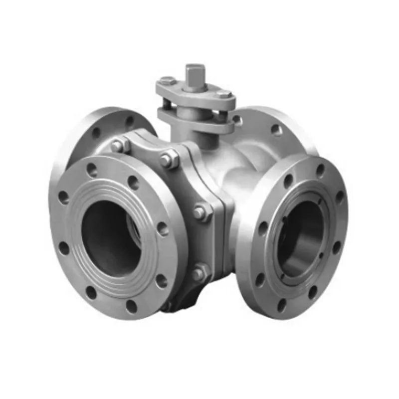
AI-based visual inspection for ball valve seats uses controlled imaging, machine-learning models, and automated classification to identify visible defects before assembly or shipment. It can detect scratches, pits, contamination, edge damage, incomplete machining, discoloration, and geometry-related visual anomalies. Unlike pressure, leak, and acoustic-emission testing, visual inspection evaluates the observed surface and shape rather than directly proving pressure retention or sealing performance.
A typical system contains an industrial camera, lens, lighting module, fixture, positioning mechanism, processing computer, inspection software, and production interface. The component is placed in a repeatable orientation, one or more images are captured, and the software compares the image against defined acceptance criteria. The output may be a pass, fail, review, defect category, confidence score, image record, and linked production serial number.
For ball valve seat inspection, the application is technically demanding because the seat may be white, translucent, dark, metallic, polished, curved, or internally recessed. PTFE seats can show embedded particles, compression marks, flash, scratches, and edge deformation, while metal seats may exhibit machining lines, coating variation, impact marks, burrs, and local corrosion. A successful system therefore depends on optical design and validation data, not only on the AI model.
The seat controls the contact relationship between the ball and the valve body. A visible defect may create a leakage path, increase operating torque, accelerate wear, damage the ball surface, or cause rejection during final pressure testing. Some failures are obvious during visual inspection, while others become measurable only after assembly and functional testing.
The most useful inspection program divides defects into categories with different severity levels. Critical defects may include a missing seat, a fractured sealing edge, a deep gouge across the sealing band, or contamination that prevents correct seating. Major defects can include excessive surface marks, local deformation, machining damage, or dimensional irregularity outside the drawing tolerance. Minor findings may include nonfunctional cosmetic variation, provided the customer specification allows it.
| Defect category | Typical visual indication | AI inspection capability | Required confirmation |
|---|---|---|---|
| Scratches and grooves | Linear marks crossing or approaching the sealing band | Detects line length, width, direction, and location | Micrometer, profilometer, or functional test |
| Pits and voids | Dark or bright isolated areas | Measures area, count, and distribution | Dimensional or material review |
| Contamination | Fibers, chips, oil residue, dust, or embedded particles | Segments foreign material by contrast and shape | Cleaning and repeat inspection |
| Edge damage | Chipped, torn, rolled, or irregular perimeter | Compares edge geometry with a trained reference | Dimensional inspection |
| Flash or burrs | Raised material around a molded or machined edge | Detects abnormal protrusions and shadows | Gauge, microscope, or tactile check |
| Deformation | Ovality, compression marks, or uneven profile | Estimates contour deviation from a reference image | Coordinate measurement or gauge |
| Surface discoloration | Local color or reflectivity change | Classifies abnormal regions when lighting is controlled | Material or process investigation |
| Missing or wrong component | Incorrect seat type, size, or orientation | Uses shape, text, contour, and feature recognition | Barcode and assembly verification |
AI should not be configured to classify every visual difference as a failure. Acceptance criteria must connect defect size and position with engineering risk. For example, a 0.2-millimeter mark outside the sealing band may have a different consequence from a 0.2-millimeter groove crossing the sealing band, so the inspection model should include location-based rules.
The first step is to convert drawings, customer specifications, and quality plans into measurable inspection rules. The specification should identify seat material, nominal size, sealing-band location, allowable surface marks, dimensional limits, contamination limits, and image areas that require inspection.
A practical inspection plan also defines the decision classes. A two-class model may classify only pass and fail, while a production system often benefits from additional categories such as scratch, contamination, edge damage, wrong part, deformation, and manual review. Separate classes help manufacturers identify process causes instead of collecting only a rejection number.
The quality team should establish a defect library using production samples. A useful pilot dataset may contain several hundred to several thousand images, including acceptable variation, confirmed defects, different batches, different operators, and changes in lighting or tool wear. The exact dataset size depends on defect diversity, but each critical defect class should be represented across multiple lots rather than repeated images of one sample.
The camera must provide enough resolution to display the smallest defect that matters. If a 0.1-millimeter defect must be detected across a 50-millimeter inspection field, the optical system should provide substantially more than one pixel across that defect; in practice, engineers may target 5–10 pixels across the smallest critical feature before model training. This requirement affects sensor resolution, lens selection, working distance, and field of view.
Lighting is often the most difficult part of machine vision for valve manufacturing. Polished metal reflects the light source, while PTFE can produce low-contrast marks, glare, or diffuse brightness changes. Ring lighting, coaxial lighting, dome lighting, backlighting, dark-field lighting, or multiple angled sources may be tested, with the final design selected from measured contrast and repeatability rather than visual appearance alone.
A seat may require several views because one image cannot expose the complete sealing surface. A rotary fixture can index the component through fixed angular positions, while a camera system can inspect the top face, inner diameter, outer edge, and sealing band. The inspection cycle should include loading, positioning, image capture, processing, result confirmation, and reject handling within the available takt time.
Before AI classification, the system should control exposure, focus, white balance, camera position, and part orientation. Image normalization can reduce variation caused by brightness or background changes, but it cannot correct poor lighting or unstable fixtures. A barcode, QR code, or manufacturing execution system identifier can associate each image with a work order, material lot, operator, machine, and inspection timestamp.
For reflective seats, image capture may use multiple exposures or several light angles. The software can combine these views to separate actual surface damage from glare. However, additional images increase processing time and data volume, so the manufacturer must verify that the selected configuration meets the production takt.
The AI model may use supervised deep learning, anomaly detection, or a hybrid approach combining image classification with geometric and dimensional rules. Supervised classification is suitable when defect categories are known and labeled samples are available. Anomaly detection can identify unusual patterns when acceptable samples are easier to collect than every possible defect type.
The system should not rely only on a confidence score. A production decision can combine AI confidence with region-of-interest rules, measured dimensions, component identity, and image quality checks. For example, an image with insufficient focus or an obstructed sealing band should be sent to manual review rather than automatically passed.
Model validation should use separate training, validation, and test sets. The test set should contain images from different production dates and, where possible, different tools or camera sessions. Manufacturers should report false-accept rates, false-reject rates, repeatability, inspection cycle time, and manual-review percentage instead of presenting only overall accuracy.
After classification, the system sends a result to the PLC or line controller. A failed part may be diverted to a locked reject bin, marked, held for review, or routed to cleaning and reinspection. The disposition logic should prevent a failed seat from returning to the production flow without a documented release.
A traceability record may include the part number, serial number, material lot, image files, defect class, model version, operator ID, timestamp, equipment ID, and final disposition. MES integration allows production managers to link inspection results with machining batches, molding parameters, assembly stations, pressure tests, and customer shipment records.
An effective inspection sequence usually follows a controlled order:
This sequence matters because AI cannot compensate for contamination, poor focus, or inconsistent placement. The system should also be challenged with known defect samples, including defects near the decision boundary. Acceptance testing should verify detection across the full specified seat range, not only one nominal size.
AI visual inspection and conventional validation methods should be treated as complementary layers. Each method observes a different physical property, and combining them reduces the risk of accepting a part that passes one test but fails another.
| Method | Detects effectively | May not detect alone |
|---|---|---|
| AI visual inspection | Surface scratches, pits, contamination, edge damage, missing features, wrong orientation, visible deformation | Internal leakage paths, pressure-induced deformation, some subsurface flaws |
| Dimensional inspection | Diameter, thickness, height, roundness, position, and tolerance compliance | Surface contamination, some texture defects, pressure-retention behavior |
| Pressure testing | Body integrity, pressure retention, gross leakage, assembly sealing under test conditions | Cosmetic defects, localized damage not activated by test setup |
| Leak testing | Leakage rate through defined interfaces or sealing surfaces | Defects that do not cause leakage under the selected pressure, medium, or time |
| Acoustic-emission testing | Energy released by active cracking, deformation, or leakage-related events under stress | Stable surface damage, contamination, geometry errors, and inactive defects |
| Torque or functional testing | Operating resistance, movement, and assembly-related problems | Small visible defects that do not yet affect torque |
Pressure and leak testing remain essential for applicable valve designs and customer requirements. The test pressure, medium, duration, acceptance limit, and configuration should follow the governing specification or approved quality plan. AI can reduce the number of visibly defective seats entering assembly, but it cannot be presented as a substitute for a validated pressure-retention or leakage test.
Acoustic-emission testing has a different role. It may detect active mechanisms that release measurable elastic energy during loading, but it does not replace surface inspection for contamination, scratches, burrs, or incorrect geometry. A manufacturer selecting between methods should map each known failure mode to the test most capable of exposing it.
A production system should specify camera resolution, lens distortion, depth of field, exposure stability, lighting life, fixture repeatability, and changeover time. If the product range includes multiple seat sizes, the fixture may need adjustable nests, recipe-controlled positioning, or interchangeable tooling. A changeover target should be measured in minutes and verified across repeated production runs.
Rotation is important when the sealing surface is circular or partially hidden. The system may use continuous rotation, indexed rotation, or multiple fixed cameras. Engineers should calculate the number of views from the seat geometry and minimum surface coverage, then verify coverage by marking the component and confirming that every region appears in at least one usable image.
Edge computing keeps image processing near the production line and reduces dependence on an external network. This can support response times measured in milliseconds to seconds, depending on image count, model complexity, hardware, and required reporting. The system should continue safe operation if the factory network is interrupted, while synchronizing records after connectivity returns.
Software requirements should include role-based access, recipe management, audit logs, model version control, image retention, defect review, and controlled retraining. A new model should not be placed into production without approval, baseline comparison, and documented validation against the previous model. Retraining should follow a defined governance process rather than occur after every isolated false reject.
The PLC should receive a clear result code and interlock the next process where necessary. A reject-handling design must prevent mixed good and failed parts, especially when the inspection rate is high and operators handle multiple components simultaneously. Sensors should confirm that the reject gate, bin, or marking device completed its action.
MES connectivity allows manufacturers to track defect rates by seat material, supplier, mold, machining center, tool life, shift, and production order. This turns isolated images into process-control data. For example, a rising rate of edge damage after a tooling change may identify a maintenance issue before final leak-test failures increase.
Manual inspection remains useful for engineering samples, low-volume products, defect confirmation, and abnormal conditions. It is limited by operator fatigue, visual acuity, inspection posture, lighting variation, and inconsistent interpretation of borderline defects. These limitations become more significant when the same seat must be inspected repeatedly across multiple shifts.
AI inspection provides consistent image conditions and a recorded decision path. It can also compare defect rates by production interval and preserve images for customer-dispute review. However, a poorly designed automated system can create systematic errors, including repeated false rejects caused by glare or repeated false accepts caused by an unrepresented defect class.
The correct comparison is therefore not “AI versus people” in isolation. A practical setup uses AI for repeatable screening, trained personnel for exception review, and conventional tests for performance validation. Manufacturers should compare missed-defect rates, false-reject rates, cycle time, labor hours, reinspection volume, and downstream leak-test failures during a controlled pilot.
An automated valve inspection system should be selected from the production risk backward. Start with the seat materials, product sizes, defect classes, required takt time, traceability level, and customer documentation requirements. Then assess whether the supplier can demonstrate the system with actual seats and verified defect samples.
| Evaluation factor | Questions for the supplier |
|---|---|
| Detection scope | Which surface, geometry, contamination, and identity defects are included? |
| Optical design | What camera resolution, lens, lighting, and number of views are proposed? |
| Validation | Are false accepts, false rejects, repeatability, and cycle time measured on customer samples? |
| Integration | Can the system communicate with PLC, MES, barcode, and reject equipment? |
| Traceability | Are images, model versions, operators, lots, and dispositions stored? |
| Changeover | How are recipes managed for different seat materials and sizes? |
| Maintenance | What are the cleaning, calibration, lighting replacement, and backup procedures? |
| Governance | How are retraining, model approval, and software changes controlled? |
| Acceptance testing | Does the supplier provide a documented factory-acceptance and site-acceptance protocol? |
| Total cost | What are equipment, integration, training, maintenance, storage, and revalidation costs? |
A supplier evaluation should include a factory-acceptance test using known good parts and seeded defects. The test should define the minimum detectable defect, maximum false-reject rate, inspection cycle time, image-retention policy, and communication behavior during faults. Site acceptance should repeat the evaluation under actual production lighting, vibration, operator handling, and network conditions.
The financial case depends on production volume and current failure costs. A planning model can estimate annual benefit with the following structure:
Annual benefit = avoided downstream defects + reduced rework labor + reduced inspection labor + fewer customer claims − system operating cost.
For example, assume a factory inspects 600,000 seats annually and has a downstream defect escape rate of 0.35%. That equals 2,100 potentially affected parts. If each escaped defect creates an average internal or customer-related cost of USD 45, the exposure is USD 94,500 before considering reputation or delivery disruption.
If a validated AI system reduces the relevant escape rate by 60%, the avoided cost in this example would be approximately USD 56,700 per year. If the project also removes 1,200 hours of repetitive inspection at a fully loaded labor cost of USD 12 per hour, the additional labor benefit is USD 14,400. These are planning assumptions, not universal results, and should be replaced with factory data during a pilot.
A complete total-cost model must include camera and lighting equipment, fixtures, industrial computers, software licenses, integration engineering, MES work, operator training, spare parts, calibration, image storage, model revalidation, and downtime during installation. If the initial project cost is USD 85,000 and measurable annual savings are USD 71,100, the simple payback period is approximately 14.4 months before financing and tax effects.
Delivery risk also belongs in the calculation. A failed inspection project can delay production if the line depends on a new fixture, a network connection, or unapproved software. Buyers should request a milestone plan covering sample submission, optical proof-of-concept, model training, factory acceptance, shipment, installation, site acceptance, and production release.
China has a large concentration of valve manufacturers, machining suppliers, automation integrators, camera vendors, and industrial software providers. This ecosystem can support local service and shorter equipment logistics, but buyer evaluation still needs measurable controls. A supplier should be assessed by its ability to handle the specific seat material, defect library, production takt, traceability rules, and customer testing requirements.
Chenyu Valve is based in Longwan District, Wenzhou, an area associated with China’s valve manufacturing sector. Its published company information identifies stainless-steel and carbon-steel valves among its products, including ball, gate, globe, check, strainer, and needle valves, with applications listed across petrochemical, metallurgy, power, environmental protection, food, pharmaceutical, and construction industries. The company also states that normal-size valves may be stocked and that typical lead time depends on quantity, with a general range of 15–35 days. (chenyuvalves.com)
For a manufacturer such as Chenyu Valve, AI inspection should be connected to the existing quality plan rather than operated as a separate demonstration station. The implementation should identify which seat types are produced, which defects are most frequently found, and where inspection evidence is needed before assembly or shipment. A pilot can begin with one valve family, one seat material, and one production cell before expanding to additional sizes and designs.
Buyers sourcing from ball valve china suppliers should request records that distinguish visual inspection from pressure and leak testing. They should also ask how nonconforming parts are segregated, how inspection images are retained, how model updates are approved, and how production data is linked to the shipment lot. These details directly affect compliance, delivery risk, and the cost of resolving disputes after delivery.
Before approving an AI ball valve seat inspection project, confirm the following:
AI-Based Visual Inspection for Ball Valve Seats – A New Standard Emerging in China is best understood as a layered quality-control method, not a replacement for every conventional valve test. Controlled imaging and AI classification can identify surface damage, contamination, edge defects, wrong components, and visible geometry anomalies before those problems reach assembly or shipment. Pressure testing, leak testing, dimensional inspection, and acoustic-emission testing remain necessary because they evaluate different failure mechanisms.
The next step for a valve manufacturer is a documented pilot using real seats, defined defect limits, multiple lighting conditions, and a separate validation dataset. Measure false accepts, false rejects, cycle time, manual-review rate, downstream test failures, and image traceability for at least several production lots. For Chenyu Valve and other Chinese manufacturers, the business case should then combine defect-escape costs, rework labor, customer claims, implementation expense, delivery exposure, and ongoing model governance before approving full-line deployment.
A: Chenyu Valve is identified as a valve manufacturer and factory supplying stainless-steel and carbon-steel ball valves. Buyers should confirm during quotation whether AI visual inspection is included for the specific ball valve project and request sample inspection images, defect criteria, and traceability records.
A: Specify the valve type, nominal size, seat material, sealing-surface defect limits, applicable standards, required inspection views, image-retention requirements, and whether visual results must be linked with dimensional, pressure, or leak-test records.
A: No. AI inspection can identify visible scratches, contamination, edge damage, wrong components, and geometry anomalies, but it does not directly prove pressure retention or leakage performance. Pressure, leak, dimensional, and functional tests should remain part of the approved quality plan.
A: The closest match is Chenyu Valve’s ball valve range, including stainless-steel, carbon-steel, cast, and threaded ball valve products shown on its website. The inspection method should be validated separately for each seat material, valve size, sealing design, and surface finish.
A: Request the manufacturer or factory status, available sizes and materials, applicable standards, inspection and test documentation, nonconforming-part handling, traceability format, stock availability, lead time, and quotation terms. Chenyu Valve states that normal-size valves may be stocked and that typical lead time generally ranges from 15 to 35 days depending on quantity.
Related News
Related Products
Navigation
Navigation
Contact Us
Contact Us
E-mail: abby_zcyvalves@zcyvalve.com
Mobile: +86 133 9699 8344
WeChat: +86 158 8872 1646
WhatsApp: +8615888721646
Add.: Room 401, 4F, NO.1017, JinHai 3rd Avenue, Kong Gang New Zone, Yong Xing Street, Long Wan District, Wen Zhou City, Zhe Jiang, P.R. China.


